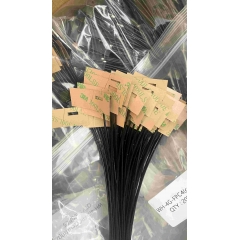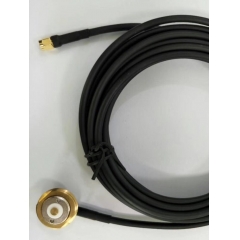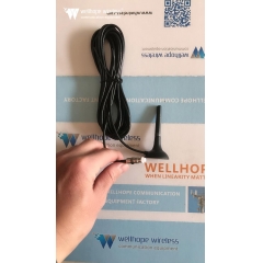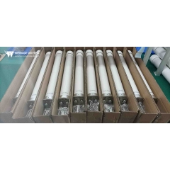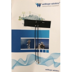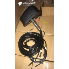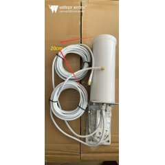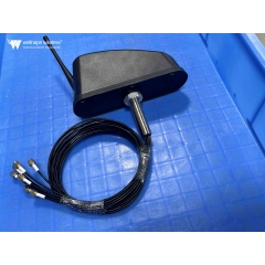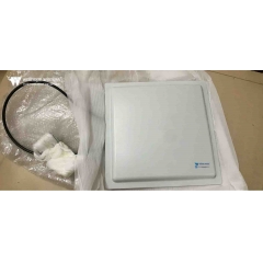

 Антенна WiFi-маршрутизатора
Поляризация антенны: что это такое и почему это важно
Расчетное время чтения: 15 минут
Каждый инженер-электронщик знает, что антенны передают и принимают сигналы в виде электромагнитных волн (волн электромагнитной энергии), свойства которых можно описать уравнениями Максвелла. Как и многие специализированные технические темы, мы можем рассматривать эти уравнения, а также правила распространения и характеристики электромагнитных волн с разных точек зрения — от относительно простых качественных описаний до сложных, детализированных математических формул.
Поляризация является одной из многочисленных характеристик распространения электромагнитной энергии. Ее влияние и степень необходимости учета значительно различаются в разных сценариях применения и соответствующих конструкциях антенн. Основные принципы поляризации применимы ко всему электромагнитному излучению, включая радиочастотные (RF)/беспроводные сигналы и световую энергию, а поляризация широко используется в области оптики. В этой статье рассматривается только радиочастотный диапазон.
Что такое поляризация антенны?
Чтобы понять поляризацию, необходимо сначала освоить основы электромагнитных волн. Электромагнитная волна состоит из электрического поля (E-поля) и магнитного поля (H-поля), распространяющихся в одном направлении. Электрическое и магнитное поля перпендикулярны друг другу, и оба они перпендикулярны направлению распространения плоской волны.
Поляризация определяется как плоскость колебаний электрического поля при наблюдении от передающей стороны в направлении распространения волны. При горизонтальной поляризации электрическое поле колеблется из стороны в сторону в горизонтальной плоскости; при вертикальной поляризации электрическое поле колеблется вверх и вниз в вертикальной плоскости (см. рисунок 1).

Рисунок 1: Электромагнитная волна с взаимно перпендикулярными компонентами электрического и магнитного полей
Передающая и принимающая антенны образуют антенную пару, и характеристики приемопередачи достигают максимума, когда обе имеют одинаковые плоскости поляризации. В качестве отсылки к знаменитой фразе из фильма Чужой 1979 года — «В космосе никто не услышит ваш крик» — в открытом космосе не существует принципиального различия между горизонтальной и вертикальной поляризацией. Тем не менее теории согласования поляризации и выравнивания антенн по-прежнему верны для максимальной передачи и приема энергии сигнала.
Линейная и круговая поляризация
Электромагнитные волны имеют несколько режимов поляризации:
- Базовая линейная поляризация включает две взаимно ортогональные (перпендикулярные) формы поляризации (см. рисунок 2). Теоретически антенна с горизонтальной поляризацией не может принять сигнал, излучаемый передающей антенной с вертикальной поляризацией, работающей на той же частоте, и наоборот. Чем ближе ориентации поляризации двух антенн, тем сильнее принимаемый сигнал; эффективность передачи энергии сигнала достигает максимума при идеальном согласовании поляризации.

Рисунок 2: Линейная поляризация имеет две взаимно ортогональные формы поляризации
- Наклонная поляризация является разновидностью линейной поляризации. Как и стандартная горизонтальная и вертикальная поляризация, это определение применяется только к наземным сценариям. Наклонная поляризация образует угол ±45° относительно горизонтальной плоскости. Хотя наклонная поляризация является по сути линейной, когда специалисты отрасли говорят «линейная поляризация», они обычно имеют в виду только антенны с горизонтальной или вертикальной поляризацией.
- Сигналы, излучаемые или принимаемые антеннами с наклонной поляризацией, могут приниматься антеннами с исключительно горизонтальной или вертикальной поляризацией, хотя и с определенной потерей сигнала. Антенны с наклонной поляризацией идеально подходят для случаев, когда состояние поляризации одной или обеих антенн неизвестно или когда поляризация изменяется во время работы.
- Круговая поляризация (CP) сложнее линейной поляризации. В этом режиме поляризации вектор электрического поля непрерывно вращается по мере распространения сигнала. Если смотреть наружу от передающего конца, вращение вектора электрического поля по часовой стрелке называется правой круговой поляризацией (RHCP); вращение против часовой стрелки — левой круговой поляризацией (LHCP) (см. рисунок 3).

Рисунок 3: Вектор электрического поля электромагнитных волн с круговой поляризацией вращается, разделяясь на правый и левый типы
Сигналы с круговой поляризацией формируются путем наложения двух ортогональных электромагнитных волн со сдвигом фазы 90°. Для создания круговой поляризации должны выполняться три условия: электрическое поле должно содержать две ортогональные компоненты; между двумя компонентами должна быть разность фаз 90°; обе компоненты должны иметь одинаковую амплитуду. Спиральные антенны обеспечивают простое решение для создания волн с круговой поляризацией.
- Эллиптическая поляризация (EP) является производной от круговой поляризации. Как и волны с круговой поляризацией, волны с эллиптической поляризацией формируются из двух линейно поляризованных волн. Эллиптическая поляризация возникает, когда две взаимно перпендикулярные линейно поляризованные волны с неодинаковой амплитудой накладываются друг на друга.
Степень несогласования поляризации между двумя антеннами количественно определяется коэффициентом потерь поляризации (PLF), измеряемым в децибелах (dB). Его значение определяется углом поляризации между передающей и принимающей антеннами. Теоретически PLF равен 0 dB при идеальном согласовании поляризации (нулевые потери); если две антенны полностью ортогонально поляризованы, PLF стремится к бесконечности (полное затухание сигнала).
Однако в реальных приложениях антенны не могут достичь идеально согласованной или полностью ортогональной поляризации. Несовпадение при механической установке, ошибки эксплуатации, искажения канала, многолучевые отражения и другие факторы вызывают угловое отклонение направления поляризации передаваемого электрического поля. Даже если две антенны разработаны для ортогональной поляризации, на практике все равно возникает утечка кросс-поляризации от 10 до 30 dB и выше. В некоторых сценариях этот просочившийся сигнал достаточно силен, чтобы мешать демодуляции требуемого сигнала.
И наоборот, даже при идеальной поляризации и точном выравнивании двух антенн реальные факторы окружающей среды могут привести к увеличению PLF до 10 dB, 20 dB или выше, ухудшая прием сигнала. Проще говоря, непреднамеренная кросс-поляризация и высокие коэффициенты потерь поляризации вызывают два неблагоприятных эффекта: они создают мешающие сигналы и ослабляют полезный целевой сигнал.
Почему характеристики поляризации важны
Поляризация подчиняется двунаправленному правилу: чем точнее совпадают и согласуются типы поляризации двух антенн, тем выше мощность принимаемого сигнала. Напротив, плохое согласование поляризации затрудняет прием достаточного полезного сигнала как целевыми приемниками, так и приемниками помех. В большинстве сценариев беспроводной канал изменяет состояние поляризации передаваемого сигнала или одна либо обе приемопередающие системы не могут поддерживать фиксированную стационарную ориентацию антенны.
Выбор режима поляризации обычно определяется условиями установки и атмосферными условиями распространения. Например, антенны с горизонтальной поляризацией обеспечивают лучшие характеристики сигнала и более стабильную поляризацию при установке рядом с потолками; напротив, антенны с вертикальной поляризацией, установленные у боковых стен, демонстрируют поведение поляризации, более близкое к их номинальным проектным характеристикам.
Обычные дипольные антенны (стандартные диполи / сложенные диполи) работают с горизонтальной поляризацией при традиционном монтаже (см. рисунок 4). При необходимости соответствия определенному режиму поляризации антенну можно повернуть на 90°, чтобы переключиться на вертикальную поляризацию (см. рисунок 5).
ФОРМА \* ОБЪЕДИНИТЬФОРМАТ
Рисунок 4: Дипольные антенны обычно устанавливаются горизонтально на мачтах для горизонтальной поляризации
ФОРМА \* ОБЪЕДИНИТЬФОРМАТ
Рисунок 5: Дипольные антенны могут устанавливаться вертикально на мачтах для вертикальной поляризации, когда этого требует применение
Вертикальная поляризация широко используется в портативных рациях, например в устройствах, которые носят сотрудники аварийно-спасательных служб. Это связано с тем, что большинство вертикально поляризованных радиоантенн имеют всенаправленные диаграммы излучения — это означает, что пользователям не нужно корректировать азимут антенны даже при постоянном изменении ориентации портативного устройства.
Большинство антенн работающих в диапазоне высоких частот (HF) от 3 до 30 МГц используют простые конструкции длиннопроводных антенн, натянутых горизонтально между опорами. Их большие физические размеры определяются соответствующей длиной волны (10–100 метров), и такие антенны имеют естественную горизонтальную поляризацию.
Любопытно, что диапазон получил название «высокая частота» несколько десятилетий назад, когда частота 30 МГц считалась высокой. Хотя сегодня это обозначение кажется устаревшим, оно остается официальным обозначением диапазона, определенным Международным союзом электросвязи (ITU), и по-прежнему повсеместно используется.
Диапазон средних волн (MW) охватывает частоты от 300 кГц до 3 МГц. Поляризация, выбираемая вещательными станциями в этом диапазоне, зависит от того, использует ли станция поверхностные волны для покрытия сильным сигналом на коротких расстояниях или ионосферные пространственные волны для передачи на большие расстояния. В целом антенны с вертикальной поляризацией обеспечивают превосходное распространение поверхностных волн, тогда как антенны с горизонтальной поляризацией лучше подходят для связи с использованием пространственных волн.
Спутниковая связь в значительной степени опирается на круговую поляризацию. Спутники постоянно изменяют свое положение относительно наземных станций и других спутников. Эффективность передачи сигнала достигает максимума, когда и передающая, и приемная стороны используют антенны с круговой поляризацией; сочетание антенн с линейной поляризацией и антенн с круговой поляризацией работает, но приводит к измеримым потерям из-за коэффициента поляризации.
Характеристики поляризации также имеют решающее значение для систем 5G. Некоторые антенные решетки 5G с многократным входом и многократным выходом (MIMO) используют технологию поляризации для более эффективного применения ресурсов спектра, повышая скорость передачи данных. Это достигается путем объединения различных режимов поляризации сигналов с пространственным мультиплексированием антенн (пространственным разнесением). Такие системы одновременно передают два независимых потока данных, причем каждый поток подается на отдельные антенны с взаимно ортогональной поляризацией, что позволяет приемнику отдельно демодулировать два потока. Хотя неидеальные факторы, включая пути распространения, искажения канала, отражения и многолучевые эффекты, создают небольшие помехи между поляризациями, приемники компенсируют их внутри системы.
Заключение
Поляризация является важной, но часто недооцениваемой характеристикой антенн. Линейная поляризация (включая горизонтальный и вертикальный варианты), наклонная поляризация, круговая поляризация и эллиптическая поляризация каждая подходят для различных сценариев применения. Относительная ориентация и степень согласования антенн на передающей и приемной сторонах напрямую определяют общую производительность полного радиочастотного канала. Широкий ассортимент стандартных антенн, охватывающих все типы поляризации и диапазоны радиочастот, доступен на рынке для реализации схем поляризации, адаптированных под все целевые применения.